
Using induction, it is possible to transfer electrical energy remotely, without any wires. Here is a wireless power transmitter circuit, using a Royer oscillator.

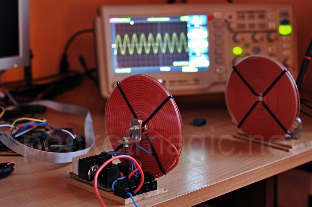
Similar to the Radio broadcasting technology, I have designed an emitter and a receiver. They are both tuned to work on the same frequency, in this case 63.1KHz. Their purpose is to transport electrical energy.
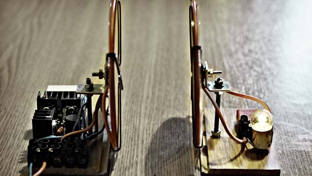
The oscillator in the emitter is a Royer push and pull type, using two IRF2807 mosfets. The emitter coil, is a circular 18 turns coil, with a tap at the middle (9+9 turns).
The receiver, uses a similar 18 turns circular coil, but no middle tap is required. I’ve used PVC insulated 1.5mm copper wire for both coils. A 440nF capacitor is connected in parallel to this coil, and then the load – a simply 12V bulb. See the circuit diagram for more details.
Circuit diagram:
![]()
This is a good alternative to recharging my autonomous robot . The robot can automatically detect the power emitter, and approach it to recharge its batteries.
Note: In free space, all electromagnetic waves (radio, light, X-rays, etc.) obey the inverse-square law which states that the power density of an electromagnetic wave is proportional to the inverse of the square of the distance from a point source.
Doubling the distance from a transmitter means that the power density of the radiated wave at that new location is reduced to one-quarter of its previous value.
The power density per surface unit is proportional to the product of the electric and magnetic field strengths. Thus, doubling the propagation path distance from the transmitter reduces each of their received field strengths over a free-space path by one-half. Radio propagation.

Witricity!
Actually, I had a different name in mind 🙂
what was ur input voltage ? i also did this project in college so i was curious to findout ur efficiency ?
12-24V . Efficiency will be measured soon but seems to be high.
Would be interesting if you could measure efficiency for different distance and misalignment. Does the primary current rush when the secondary side is removed, or does it stop? I.e. how is the reflected impedance related to the airgap, secondary load resistance etc?
@Tomas, hope to find some time for all this, soon.
@Radu Motisan, when you have studied the efficiency with the coils you have now, it would be really interesting to see how much it could be increased by using litz wire instead of solid copper wire. Maybe I’d better build one myself and try, your circuit diagram is excellent!
Thanks, Tomas. The red wire is actually litz, but the internal thin wires are not insulated from each other. One can use regular emailed copper wire , and twist several wires together for the desired size.
I want make similar project and I want more details about this so please help me to make concept of your or our project clear
All the details, including circuit diagram are presented in the post.
cool….
can the power be focused? just like a laser beam line sending from source coil to target coil?
Ar merge si cu driver ZVS ?
Salut Stelian, ZVS e chiar un oscilator Royer, deci asta am folosit si eu aici, intr-o varianta usor imbunatatita.
Salut Radu, ce curent maxim poti transfera, am vazut pe schema ca scrie max 10 A ? Se poate 10A ? Multumesc
Salut Bogdan,
Din pacate nici pana acum nu am facut masuratorile, asa cum scriam in articol ca doresc sa fac.
La cum vad eu lucrurile, poti fara probleme sa ajungi si la 10A intensitate. OScilatoarele de acest tip (royer) au servit cu succes puteri de pana la 300W , ar trebui sa mearga si in acest caz.
Hi Radu
Any idea what current the demonstration was drawing?
On your schematic you show a 1000uH 10A inductor but I can’t see anything this big on your pcb in the video.
Thanks
Warren
Yes, my inductor was for smaller current, still you should use one rated for higher power to make sure the circuit will run cool for longer amounts of time.
I didn’t do the current measurements yet, sorry, I need to do them and post result on efficiency. Hope will be able to do this soon.
the input voltage is in dc or ac actually?
the circuit diagram clearly shows a + and a – . so it is DC input
give me detail information & file of that wireless projects
Hi
I am first year EE student. Because I want to understand the circuit more, I start reading electronics book and it was really nice and helpful to understand the basics of some of the components in the digram. But till now I did not fully get it. Please, it will be kind from you if you explain your circuit…
This is magnetic induction. It has a limited range and not too practical…This is not what you are looking for… You want to send high power energy with no restrictions to very long distances using longitudinal electric waves, just like Nikola Tesla did.
Hi
how did u take a center tap in the transmitter coil?
@Deepal: it is so easy! You wind 18 turns, then puncture the plastic coil former, at the 9th turn, and solder an external connector, that would be the center tap.
So the emitter and transmitter coils are at first identical, until you puncture the emitter to create the center tap. 18 turns both as explained above.
If you build this send me pics so I can post them here.
What did you use for the 10 volt zener diodes?
Also, do you think this would work if I used slightly different dimensions for the coils, but stayed with the same number of turns and kept both proportional? Like, if I just used 22 gauge hookup wire for the coil, in stead of 1.5 mm wire?
P.S. Keep experimenting, bro! This type of research is very cool. Just for a suggestion, to see if you could make it work, I remember reading where someone was making a circuit like this to power a flyback transformer. It would be like transmitting a few kV wirelessly.
Hi John,
I don’t remember the part name for the 10V zeners, but they were like 0.5W .
You can use any zeners in the 10V-16V interval, so choose what you have.
Yes you can use different wire for the coils.
Thanks for all the help, Motisan! I’ll check and see the transition frequency of the IRF2807, just in case: AWG 22 wire is pretty thin, and I’m worried the frequency may be too high for them to handle. Plus, I really love how you laid out the circuit in the videos and pictures. Whenever I make a project, half the fun in it is in making it look awesome or futuristic, and this one really hits the nail on the head.
If you like, I’d love to talk more with you about your ideas and experiments. It’s so hard to find any good circuits or ideas for a concept like remote power transmission, which has been around for well over 100 years. I ordered the parts, and am working on a few projects myself at the moment, but when I get the chance to make this (if the damned thing works right – I always mess things up!), I’ll fill you in on the results: I have an oscilloscope that I need some practice using, so I could do my best to tell you the efficiency and the waveform. I might try to adjust it to make a sawtooth waveform, which (because the magnetic field around the coil collapses so much more abruptly) can transmit power more efficiently.
Sorry if I am talking too much, I have a bad habit of doing that.
the capacitor we are using is ac or dc?
to avneet, actually, its just a film capacitor and it stores a very little electric charge so its not necessary for it to be polar, it doesnt have any polarity so just ask for a capacitor and they will give you that,
actually i have used ac capacitor of 44uf,250 v & the power transmitted from transmitter to receiver is about 1-2v
which lights up only led so what should i do to light up 12v bulb & one more question how can i increase the range of wireless power transmitter
to increase the range, you should try to increase the diameter of the coils.
regarding those center tap, i cant still understand how to have the tap. if im going to wind the wires at about 19 turns, then unfold it again and find the center by measuring, will it do?
im wondering because like what you did in your video, the center tap isnt actually at the center because the way you wind the wire isnt like in a coil where the wires are just in one side..
sorry, im really confused
i mean 18 turns
It will NOT work, as each turn has an increasing length – measuring it will place you way before the middle turn. So better use a transparent case like I did, and simply puncture it to insert a connector at the 9th turn.
se puede usar un condensador de 0.47uF en el receptor en ves del 0.44uF
can use a 0.47uF capacitor in the receiver in the 0.44uF see
so im just going to coil the wire and count the turns and on the 9th turn, i will just puncture the wire and insert the center tap?
in short.. the center tap is not pertaining to the length of the wire but to the number of turns of the wire right?
thanks..
hello, can i use other capacitors or should i use WIMA capacitors?
@joem, yes, you got it right.
@natan, you can try other caps as well.
Is it required for you to design your own oscillator or could you simply buy an oscillator chip and hook up the voltage regulator to it and output of it to the primary coil in parallel with the 0.47uF?
Can you do this?
Also, why did you pick a planar coil as your primary coil? Why not a single loop of copper? Are they not more efficient in setting up a better magnetic field rather than the planar coil?
Thanks!
For this oscillator I needed more than a single loop coil, to make it work.
And as for my initial question: Is it possible I use a standard oscillator chip with a single loop coil and capacitor in parallel. Would this work for a setup of this kind?
HB, what is a standard oscillator chip? 🙂
I mean an oscillator you can buy which is contained in a chip/block.
Wait a minute, how come you don’t have an oscillator? How or at what frere you driving your coil? Is this not resonant magnetic coupling?
And I’m sorry, I confused “oscillator chip” with power amplifier.
@HB actually, it oscillates ’cause it’s indicated on the description that it oscillates at 63.1 KHz.. and i think mosfets do these oscillation
@Joem: Yeah I was wondering ‘how’ it was doing the oscillation…I thought you were supposed to use a signal generator or crystal oscillator to provide the necessary signal @ whatever the frequency desired.
Anyways I got a question: What do the mosfets do in this design other than provide the oscillation? Does it amplify the current into the LC tank? Do we want a high current in the LC tank circuit end anyway? I would assume having a higher current at the primary coil LC end would create a really powerful and large magnetic field and hence increase the distance of transmission. Is this correct?
mm,, i dont know how it does but accdg to its name.. MOSFET or metal–oxide–semiconductor field-effect transistor, a device used for amplifying/switching electronic signals..
so i think it amplifies the current.. but i cant answer some of your questions, maybe we shall leaave it to the author.. thanks..
Hmm thank you Joem. I see what he’s doing now I think. This is basically a Royer Oscillator which is an oscillator that operates at high current and high frequency. Right now my design consists of a regular oscillator that I made which is fed into a power amplifier. Only problem is, the power amplifier part could be expensive so that’s why these Royer Oscillators are used most often. Please correct me if I’m wrong Radu.
@HB, another reason for using a high frequency power electronics converter to energize the primary coil is the efficiency. With an analog power amplifier, you will get terribly low efficiency.
@Radu Motisan, did you have time to test efficiency vs different air gaps etc? (just repeting my previous question:”Would be interesting if you could measure efficiency for different distance and misalignment. Does the primary current rush when the secondary side is removed, or does it stop? I.e. how is the reflected impedance related to the airgap, secondary load resistance etc?”)
@Tomas, from what I remember there was an interesting effect of power consumption in direct relation to the efficiency of the energy transfer: connecting a simple ammeter in the emitter circuit, one could see a massive current increase with the receiver properly aligned and the bulb shining, and a decrease as the receiver is moved away. The primary current will not stop, but will surely tend to a minimum, negligible value.
Tomas: Ah yes, thank you for that. I know there are a few oscillator circuits out there (Wien-Bridge, Hartley, Colpitts, Royer, etc) but I think the Royer is the only one that can achieve high frequency power oscillations…do you know any other way I can make a circuit that gives me high power (3-4 Amps) at high frequencies (from 100 KHz to 1 MHz)?
@HB, a couple of years ago I build a inductive power transfer device that was able to transfer a power of a few hundreds of watts (40 V, max 9 amps, if I remember correctly) over a distance of 5 cm with an efficiency of 87%. The resonant frequency was 20 kHz, and I used a MOSFET full bridge (H-bridge) to energize the primary coil. For the triggering signals I used a simple square wave signal generator.
@Tomas: Wow that’s very cool. Would I be able to do the same if my resonant frequency is @ 1 MHz instead? I doubt it … however, it might work with some sort of RF power BJT. Oh and why was the distance so short? Was it because your coil Q low or something?
@HB: the distance was fairly short because of the relatively low frequency. The lower the frequency, the better inductive coupling you will need between the coils to transfer reach the same power and efficiency levels. There were several reasons why I choosed 20 kHz frequency. One were hardware limitations (eaier to work with lower freq) and an other was that 20 kHz seems to be what they choose for the wireless EV charging standard.
@Tomas: I’m having a hard time proving on my paper why a higher frequency is better to use. I know there are hardware limitations but we were thinking of using around 1 MHz. Can you suggest me some theory I should look at as to why a higher frequency is better please? The only parameter frequency seems to affect in my calculations is the Q of the resonators, anything else? It also affects the impedance of my coil, jwL, and I kinda need this too to allow maximum power transfer to my load by matching the impedance of the source.
isistes windings as the issuer and resector to stay that way you move and well connected and did you use as a source
1000UH coil is necessary? which is the core of this air or coil which
Hello Radu and thank you for your prototype.
I read all the reviews and I was wondering who has come realize your prototype?
I’m still missing the 1000 uF and inductance calculation for connection to half of the primary coil to throw myself;-)
If testers had réussient this prototype and could give me some details on the implementation not to deceive me.
Thank you, didier
Hello Radu ,I have some project like you did and i want to know how do you know your device works on 63.1KHz? and what tools do you use to measure the frequency? because i had different result when i used oscilloscope and network analyzer(to know the resonance frequency for antenna).
what happens when the frequency higher or lower from 63.1KHz?
@didier: it’s very easy to build. not much to add here, you have full description and everything you need in the article.
@jess: I used a multimeter to measure frequency. You can use any frequency you want, just make sure the receiver is tuned to emitter’s frequency. For this purpose I used the receiver’s capacitor, adjusted in the LC circuit for the frequency required.
Efficiency was pretty high. i want to know how was the Induction coil turns
in which component does the frequency depends on? Can we use other mosfet ? Does this circuit can work in MHz range?
we are doing this project we need to know the complete working of this project and how each component works,please sent the website address in which we should search
Hello Radu,
Would you be interested in building one for me? Could you let me know your price and shipping to Finland? Would be an incredible help!
sinrev at gmail dot com
Thank you!
sir i am really impressed with this amazing thing of ur and i am making it for my collage project but i have little problem with that .i have to print a thesis of my own for this project which have to contain upto 80 pages so please help me for having them in one place i am wating for u r response . i am in big trouble pls help me sir
we r trying this project we are not getting the idea about transmitter coil and receiver coil , can you tell me what rating copper wire you used as soon as possible
@YESHU: 1.5mm^2 section , PVC insulated, copper wire. the receiver 18 turns. So is the emitter coil, but with a tap at the middle (so it is 9+9 turns).
Hi, may I know what is the maximum voltage and current can be transmitted and can the receiver charge up a mobile phone at 5v, 500mA? Thanks.
Hi Radu,
I can not find any 0.44uf or 440nf capacitor on ebay or other electronic websites, the standard is 0.47uf. Do you have a link where can I buy 0.44uf capacitor you used in your circuit? Can I substitute standard 0.47uf on both transmittor and receiver side? Will that make any difference? I am asking this b/c I a novice user. Thanks for your time to reply me.
@JP: yes it can.
@Mike: it is always fun to try , to experiment. this is my advice.
Thanks. Can the MKP capacitors replaced with other types of capacitor, etc electrolytic? Thanks in advance. Nice day.
Hi, may I know what is the diameter of the center of the coil? Does the number of turns affects the frequency or it will still be functioning if Im using the same number of turns and same value of cap for both side of the coils? Thank you.
@JP: other types yes, but not electrolytic.
@Jean: aprox. 1cm . the coils are not critical, but after you build them, you’ll probably need to adjust the values of the capacitors you use, to tweak the working frequency (given by LxC ).
I can only find X2 275 VAC MKP in my local stores, can those work? For example, if I fix 470 nF at the transmitter, I will need to change the value of cap at the receiver in order to have the same frequency with the transmitter part ( like your’s 440 nF)? Thanks.
Hi Radu, could you tell me how you came up with the coil size/ number of turns required?
A short answer would be: based on my previous experience, but why are you asking, Mark?
Just curious about how crucial the number of turns and the size of coil are to correct operation
Also what power rating resistors would you advise to use?
may i know what would be the cost estimate of this project?
wat is the diameter of the circular copper disc used..in this
What would happen if you reduced the size of the receiver coil to say 9 coils? Would you need to also change the number of transmitter coils?
Hello Radu. I finally realized your prototype;-) With a 12V input I of the lamp (halogen 12v 20w) 10.5v. The distance between the two coils being zero. My little problem is that the capacitor (470nF 400V) of the coil one explodes after 10 minutes! What can the future it?
merci, didier
dear Radu can you send me some soft copy of this project with circuit diagaram my mAil is { spicy_guys@hotmail.com } if u send me I thankfull to u
@didier, try using a capacitor rated for higher current. Connect 4 470nF/400 caps, as 2 series of 2, and connect those in parallel (you’ll get a total capacitance of 470nF and a max voltage of 800 this way).
@mudssar, what exactly do you need? the circuit diagram is already presented in the article.
@aswathy, take the cost of the components and the time for man work used in making it.
@ash,there is no copper disc, the transparent disc is from a CD.
@josh, you would change the frequency, I would suggest you change it in the emitter as well, then use the correct capacitor value (by calculating its value or by trial and error), in the receiver, to tune it on the right frequency. FAiling to do this would only give you a poor transfer efficiency.
@Mark, there are no crucial aspects in this design, but you MUST tune the receiver on the emitter’s frequency by varying the capacitor in the LC circuit.
Hi Radu,
I finished your schematic, but i dont know why receiver inductor is warm while i only use 1 red LED.
i winding 18 turns with smaller diameter and copper wire 0.6.
Please help me!
Regard.
The receiver inductor??? That sounds unlikely. Perhaps you meant something else.
What is the use of inductor coil in this circuit please reply its urgent
@Radu: I bought the LM7812 & IRF2807 but I have a problem in identifying the In, Com & out of the LM7812 and the Base, Emitter & Collector of the IRF2807. Please help
@bryan best place to start is to check the datasheets of the two.
@Radu: Ok. Thanks a lot. I was thinking all of them have defined terminals
please sent the full report of this project to my mail id ashipulleri@gmail.com….
please it is urgent
@Radu: I couldn’t get a byv26e diode. What do you suggest I use in place of it? Plus, can I use a 0.47uF cap in place of the 0.47 in the receiver? 0.44 is unavailable here. I have 2 of 0.22uF tho’. Can I combine?
salut.vreau sa realizez si eu acest proiect dar in loc de receiverul tau sa realizez un incarcator de telefon.crezi ca as reusi??cam la ce distanta maxima ar functiona?multumesc anticipat
salut Paul,
da, se poate face. jumatate de metru banuiesc ca ar fi limita unui timp de incarcare rezonabil.
multumesc pt. amabilitte.ai precizat distanta jumatate de metru in conditiile in care as mari diametru bobinelor rezonante?circuitele functioneaza pe baza principiului de inductie magnetica nu? multumesc pt. raspunsul anterior..
imi poti spune ce bobina sa cumpar?la mikado in brasov nu au bobina de 1000uH si pe internet am gasit una cu miez de ferita dar e folosita pt transformatoare..ma poti ajuta cu un model?
mai exact ce tip de bobina??
hi.. could yo please tell me how you fixed the frequency here?
Bonsoir Radu
I wondered about the mounting level 2:
How did you calculated your frequency (63.1 kHz)?
On most mounting Royer, the middle point (the middle wire) of the first coil is to half the length of tone while mounting, being put after nine rounds was not the same distance between the start and the end of the coil. Is there a reason?
I hope you understand what I mean views and thank you for your editing.
Didier
Salut, Didier,
It is not the length of wire that matters, but the number of turns. This is why the tap at the middle point is the middle turn, but not the middle point of the distance because of the changing radius of the coil.
Let me now if you need more details. The frequency is given by the coil and the capacitor. Change it as needed.
Radu
Hi Radu,
Thanks for this wonderful work, I want to get in touch for some help as I want to do a similar project. Many thanks,
Cheers,
Wil
Hey, I am doing my project on witricity. Your work is amazing. Could u send me an explanation on how it your circuit works…. (prathzk@gmail.com)
Once the circuit is made, Our professors are gonna grill us with questions. Like you u took 18 turns and stuff like that….
Thanx a lot… CHEERS.. 🙂
A report will do….
hi
Im project is wireless power transfer simulation by ANSOFT MAXWELL. please help me! please send information on gmail!
thank you!
Hi
could you send me an explanation on how it your circuit works.(hkeshtkar89@gmail.com)
Hossein, Pls send me your simulation… prathzk@gmail.com
hai….
I am also working on wireless power transmission. I wanted to charge a 9V battery using wireless method.. Plz help me yar
i wanted to design it…..
email: pr.25anup@gmail.com
Thanx…..
Can you try use earth for longer distances ?
Ola Radu
I solved my problem in the capacitor exploding remlaçant by 1.5UF / 350V MKP (it heats up a bit). For the output of the coil 2, the voltage is alternating, what type of diode bridge and capacitor can I use (voltage and amperage) for a DC voltage?
thank you, didier
buna radu am realizat montajul si merge dar la fel ca didier nu stiu ce diode de redresare AC-DC la receptor sa folosesc pentru frecventa aceasta. ne poti indica un tip de bobine care sa funcioneze la 0.5 A si 60khz?
Hello didier. I also need a type of diodes for rectifing the current AC-DC in the receiver..Plese post here if you find something.
Salut Paul. Poti folosi diode rapide, cum sunt BYV26E . etc/
Hello Radu M,
I appreciate your comments and info here. I had a couple of questions and will be grateful if you can answer them please.
If we use w = 1/sqrt(LC), with 63.1khz = f, the inductance of the emitter coil can be deduced to (4.01*10^-5) H. Say, instead of using 18 turns of coil, I use a solid tube of copper on the emitter side/receiver, which has inductance rated to approx (4.01*10^-5), shouldn’t that work? Will this still require the 1000uH inductance? Otherwise this would simply allow me to connect the tube to the emitter cap of 0.47uF. Same for the receiver.
Suggestions?
Thanks
Hello plz anyone reply me….
I am working on the same for charging a 9v battery. Will above circuit diagram works properly? Is that suitable for charging battery. what is extra components to be added to it. i am trying it for my final year project. Only one month left for submission. Plz any one help me in building that circuit for charging 9V battery……
Thanx…..
hI AUTHOR….
I need your email ID. I am having so many doubts….. plz help me
can u tell me the diameter of u COIL,i guess it is 10cm?
thank you very much
U can see in the picture,he use the disc shape, maybe 10-12cm
hello i have a problem … i hae made the circuit and its not working ….. i checked for 10 times and it’s wired properly
What are the components we need to change in the above circuit to work properly….. Plz any one reply me. I need to build this circuit
Hai…
Plz help me fast. i need the voltage and current ratings and
type of resistor, inductor and capacitors used in the circuit.? and
whats that withe box in reciver side in the video?
Plz reply me fast
Pravin
hai,,,,
Can i have the same 12V output with 18V 3A DC power supply to charge 12V battery….?
Suggestions….?
Thanx
I got all the components…. Bt i couldnt get 1000uH (10A) inductor
and 0.44uF Polyster Capacitor. what can i do? from which components i
can replace them?
Regards
Pravin
Please any one suggest me a online or shop to buy 0.44uF capacitor and 1000uH/10A inductor in india? can i use two 0.22uF instead of one 0.44uF capacitor?
Hi Radu M, I’m trying to build a wireless project as you’ve done as well, but I am just but a beginner.
I understand that increasing the no. of turns and diameter of coil will increase the magnetic field.
However I still have a few questions.
1. How do you limit/increase the current?
2. If a single loop coil is used, will it still work?
3. What changes do I have to make in order to power/charge a 12V battery?
Also, if I use a rectifier for the receiver circuit, what changes should I expect?
-Appreciate it for your help.
hai,,,in this circuit why you 470nf or 4.7 nf or 100nf used
The impedance and inductance coils should be much ?
realize el circuito pero al conectarlo a la fuente de 32 v y 3A no puedo aumentarlo a mas de 6 voltios y los irf 2807 se calientan demasiado
Hi, Randu. Thanks for your share.
I saw any project like this. And they used high current input for working circuit, like to transmitted. When I made it and give it 12V from trafo 1A, Voltage input was dropped! May I know minimum input current for this?
Hi Radu my name is Alec. I am currently working on the same project for my physics class and had some questions about the chosen capacitance. I see that the two transistors (from the schematic) is a .47uf capacitor that needs to be able to withstand an alternating current. But when my
group and I connect it to the power supply the capacitor gets extremely hot. Could you shed a little light on how you regulated the temperature?
Also, we are trying to make a smaller receiver coil. Is there any way we could downsize the receiver coil to match the same coupling frequency as the transmitter coil?
Thanks for your help!
@Alec, try using the lowest ESR capacitors you can find . My choice is WIMA capacitors. If this still doesn’t help, use a bank of several capacitors connected in parallel. This way the current will be shared and you get less heating. Send me pics of your setup, I’d love to see your progress so far!
i am working on transmitting 40/60 watt power at a distance of 1 meter. i need a proper power oscillator which can handle 100 watt power and generates 13.45 MHz signal. can anyone help me ??
sir can it transfer energy in 3d space ?
please help
Hi, I am wondering what are the ratings on the components. Also, if you can provide the equations and math used for this project, itll be very helpful, it will also solve the problem of the ratings of the components.
Thank you
Hi Radu !
I saw a white component in your PCB, what is that ?
thank you very much 🙂
Hi Brian. Which one?
Hi Radu , I am from Colombia (South America).
Right now i am making this project, but i want to know what is the white component located in the transmitter it looks like a cube and its totally white; i only can see three blue wires connected in that component.
I really appreciate your answer,
Have a good day.
Hi Radu , I am from Colombia (South America).
Its Brian Again 🙂
Right now i am making this project, but i want to know what is the white component located in the transmitter it looks like a cube and its totally white; i only can see three blue wires connected in that component.
I really appreciate your answer,
Have a good day.
It is a capacitor.
What would happen if you changed your coils by a standard coil you can buy in a regular electric store?