Some time after I built my first Villard multiplier , it was time to re-make this device into a reliable, bullet-proof, high voltage source. I already had a pulsed high voltage supply, my 200.000 volt marx generator , but needed a continuous HV supply.
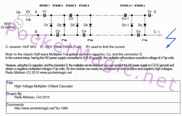
I now have all the components prepared: lots of ceramic 10nF 6KV capacitors, some high voltage fast recovery diodes, and … mineral oil. Here’s the schematic for a Half Wave cascade:
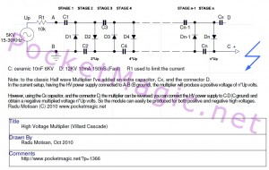
It’s written in the schematics bottom note but I will say it again. This multiplier produces a positive high voltage. I’ve added an extra capacitor, identified by Cx, for the purpose of making this module…invertible. That’s right, instead of connecting the high voltage supply (which can be a non-rectified flyback transformer) to terminals A,B (B is ground, A is the flyback output), you can connect it to C,D (C ground, D flyback non-rectified output), and you will have a Negative high voltage multiplier.
So you can easily do the switch according to your application .
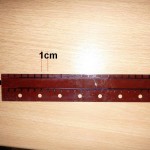
I’ve used a Russian textolite board, it’s a very good insulate used to manufacture PCB. Of course it is without the copper foil. You can use any insulating board like plastic, FB4, etc.
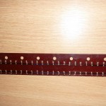
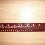
Drilled the holes for the components.
Between capacitors on the same line, I’ve allocated 1cm, and between the capacitor lines 1.5cm, for the diodes. I’ve used a marker to make signs, and after drilling the holes, I cleared the marker with some alcohol.
 |
 |
 |
Next thing to do was to plant the components: 14+14+1 capacitors (28 Stages + Cx), 28 diodes. The capacitors are 10nF 6KV Ceramic, from Ebay and the diodes are 12KV 10mA 150nS, again from Ebay.
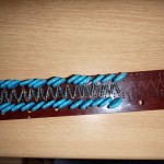 |
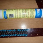 |
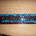 |
The first tests showed the device was producing heavy corona, so it was imperative to come with a design that would keep the components under mineral oil. The plastic tube in the second picture was the recipient for that. The unused textolit board was removed to save space.
Since the mineral oil that I have is quite old, I had to check its insulating properties with the flyback output. As you can see in the pictures, the arc is almost “rejected” by the oil surface. Good enough!
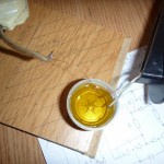 |
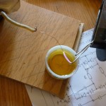 |
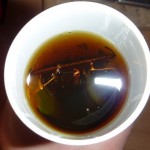 |
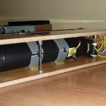
The entire multiplier board was submerged in oil. I’ve created 4 connectors, fixed with very tight screws to prevent oil leakage. A lot of hot glue secured the connectors against oil. Then I closed the plastic pipe recipient with some kind of lid and more hot glue and covered the module with black tape. The result:
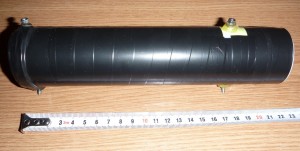
For some tests I’ve used a simple 555 driven old Flyback (without rectifier), but for some reason it doesn’t work good enough and I’ll need to use a Feedback driven Flyback (yes, the simple 2n3055 schematics). I’ve added a 10KO resistor between the flyback and the multiplier, to protect the today’s work. For the output, a TV High voltage resistor was added, so I could draw arcs in the air. Nothing spectacular, 2.5cm arcs only, as I said the Flyback supply is not good. Will test with another one and report back. Here are some pictures:
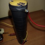 |
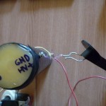 |
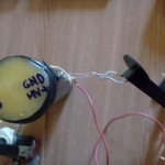 |
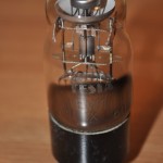
Just out of curiosity, I’ve inserted a DY86 tube (base pins connected to Multiplier Positive and the top connector to ground – reversed) and powered on the device (note: just 6Volts in to the 555 circuit/flyback), for a second then turned it off. My Radex 1706, placed at 3 cm from the tube, quickly jumped from 0.13uSv/h(background) to 23.6uSv/h and this was just a tiny fraction of what the multiplier+the DY86 can produce (not at full power).
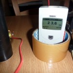 |
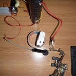 |
So far no oil leakage, and I really like this multiplier, that can be used for as a Positive HV supply (+) and as a Negative HV supply (-) if connected the other way.
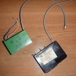
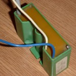
The Cx capacitor has another great advantage. You can use it to connect a TV Cascade , to this Multiplier’s Output. I’ve tried it and it works. Basically you use the TV Cascade to add a few more stages to this multiplier.
 |
 |
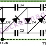 |
To connect a TV Cascade to this multiplier, do the following:
1. On the TV Cascade, connect A and D together, let’s call this terminal AD
2. Connect terminal C on the multiplier, to terminal ~ on the cascade
3. Connect terminal D on the multiplier to terminal AD on the cascade
Terminal HV on the cascade is now the new output of the combined multipliers.
Terminal B on the multiplier remains the Ground terminal.
Easy!
Related: see my Marx Generator.
EDIT:
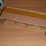
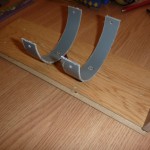
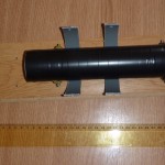
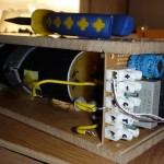
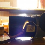
The multiplier has been packed into a nice box, with Flyback ZVS supply, limiting resistor so now I have a very high voltage supply ready to work using only 12V :
 |
 |
 |
 |
 |
 |
Unfortunately the multiplier soon failed because I was putting 10KV in while the capacitors were rated for 6KV only. One of the capacitors got conductive, short-circuiting the entire multiplier, so I had to dismantle it (including taking out the oil) and re-do everything properly. This was a good thing, since I had the chance to improve the design.


Pingback: PocketMagic » High Voltage Power supply ( 50KV for 12V in)
I am working on high voltage multiplier. I have gotten old ferrite core transformer which i drove with 555 timer circuit to generate about 10kv. I bought very high voltage diodes and capacitors to construct the multiplier. Whenever i connec this multiplier circuit there are a lot of sparks and noises. Sir what can i do to solve this problem? Besides, how can i preserve diode from swift discharge of capacitors? Pls you can leave message for me on lagunna788@yahoo.com
Hello Olaniran Badiru Babatunde,
What do you mean by “Whenever i connec this multiplier circuit there are a lot of sparks and noises” ? Please post some pics if possible to better illustrate your situation.
To protect your diodes, you need to add a 100Ohm high voltage resistor, after each diode.
Also the multiplier output connector, must have a 100KOhm high voltage resistor to limit the current.
Have a look here: http://www.pocketmagic.net/?p=1915 , look at the schematics.
I am very grateful for your inevitable information. Sir, what i mean by spark is likely to be corona-light blue fire at the leads of the component. How can i solve this problem? Sir, which type of oil can i use for insulation? Can i use transformer oil? In fact, i don’t know what you mean by mineral oir? Can i use oil for refridgeration i e inside compressor I reside in Africa, where can i get high voltage resistors? Can they be gotten inside old tv panel? Another problem i have is issue of output. I connected the output wire of tv line transformer to the output of my multiplier, i was not getting any output but i could see voltage spark at the output when the wire is not connected. Please bail me out. Thanks.
I used the output of my flyback to power tv tripler and got very high voltage from the output of the tripler from old tv but my own villard tripler i constructed with high voltage diodes and capcitors does not give much output. Sir, what is wrong?
Olaniran Badiru Babatunde, do you think it is possible to attach some pictures showing your work? It’s hard for me to tell what goes wrong without actually seeing it.
There are some things that can go wrong such as:
– some of your diodes are defective
– you have too much corona, wasting almost the entire system energy. use mineral oil, transformer oil is fine. You can also use vegetal oil (used in cooking), but heat it to eliminate any water content first.
i really thank you for your endurance. in fact i give you kudos. it seems you are providing me with all necessary information i needed. sir, i can now see your work clearly. i am using the same type of your capacitors and diodes. my own capacitors are rated 15kv, 100pF while the rating of the diodes are the same with yours. The kind of corona my own multiplier is producing is what i saw in your picture. i really want to know if i immerse the multiplier circuit inside oil where this corona will be eliminated? i try to draw out output with high voltage wire, but i am not getting anything but i could see corona at the leads of the last diode. sir what is wrong. more so, please send me your email so that i can attach pictures for clarity
i really thank you for your endurance. in fact i give you kudos. it seems you are providing me with all necessary information i needed. sir, i can now see your work clearly. i am using the same type of your capacitors and diodes. my own capacitors are rated 15kv, 1000pF while the rating of the diodes are the same with yours. The kind of corona my own multiplier is producing is what i saw in your picture. i really want to know if i immerse the multiplier circuit inside oil will this corona will be eliminated? i try to draw out output with high voltage wire, but i am not getting anything but i could see corona at the leads of the last diode. sir what is wrong. more so, please send me your email so that i can attach pictures for clarity
I like to help when possible. You really need to suppress that corona, and yes, immersing the circuit under oil will eliminate it. Before you use the oil, try to heat it above 100 degrees Celsius to eliminate water.
NO, You can’t use a vero board! The metal stripes will short circuit your multiplier, as the HV simply jumps to the first metal in its path! Be careful, this is a big mistake.
Olaniran Badiru Babatunde wrote:
> Sir, i am using vero board. I don’t know whether this is suitable for this project. I
> discovered you designed your own board. I equally noticed air has a great effect on corona!
I have found your information useful in my work and it has really helped me. I have these questions: 1. To protect the diodes, i connected resistor in series with the diode, i.e a resitor after a diode. I don’t know if it’s correct? 2. I have built 24 stages half wave, with 10KV input, i think my output should be 240kV or 120KV? 3. I designed 555 timer circuit to drive flyback transformer without rectifier sourced from old tv with 16V input, but it looks as if my output is low, what can i do to improve the output? 4. I discovered after adding resisitor to each diode the corona is greatly reduced, putting the multiplier circuit under oil, will it improve the efficiency?
hi Olaniran Badiru Babatunde,
1. yes that is correct, not more than 100Ohm resistors
2. probably 100KV max.
3. you can change the RC values of the 555 circuit, to adjust the frequency (the resistor connected to pin 2, and the capacitor )
4. you need to put the circuit under oil, and you need to drop the veroboard, and use a 100% metal free board, or else it will arc over and you will get no output
I am very grateful for all the information you have provided me. If i have discovered your site long time ago, i would have completed this project. I still have these questions: 1. It seems output of my flyback transformer is not up to 10KV, is there anyway i can roughly determine if the output is within 10KV. I want to be careful so that my flyback output does not exceed 10Kv due to the rating of diodes and capacitors( diode- 12KV, 10mA; Capacitor- 15KV, 1000pF) 2. I tried to connect TV tripler as you suggested because i need 150KV. It worked but after sometime, there was no output again. I tried using other tripler and i was getting output. What might be the cause of the failure of the tripler. 3. I notice if i can add more stages i can get more output but my components are exhusted. These components are not available in Nigeria and to order for more components like i did before will take time and money, what can i do ?
Hi Olaniran Badiru Babatunde,
To measure the voltage you would need to create a high voltage probe. Because your flyback outputs high frequency AC current, you would need a capacitive voltage divider. For DC current (rectified flybacks) it is possible to use a simpler resistive voltage divider probe.
You can read more here: http://www.pocketmagic.net/?p=1569
A simpler approach is to take the flyback output and draw an arc in air. If the discharge starts at 1cm electrode distance, than you have approx. a 10KV potential difference. So it’s 1mm for 1KV, roughly, just an approximation.
If your multiplier fails, it is probably due to diode failure. Probably you produced arcs, and this is the cause of failure. Never draw arcs with the output from a multiplier, unless you’ve also added a high voltage resistor to limit the current, as I indicated above.
Drawing arcs puts a lot of stress on the diodes, and the current in the circuit increases, as an arc is a short circuit form.
Adding more stages is impractical, as the flyback supply, will not be able to charge all the levels in your multiplier, so you should stop at 10-20 levels.
Sir, i thank you sincerely for all the useful information you have provided me. God will bless you. Sir, you still need to help me out in this area. I want to include it in my thesis the CALCULATION OF CAPACITANCE of the capacitor i.e how to calculate the capacitance of the capacitors used in my voltage multiplier.
Hello Olaniran Badiru Babatunde,
To learn how to compute the total capacitance, you can read more here: http://en.wikipedia.org/wiki/Voltage_multiplier
Good day sir, i have completed the buiding of high voltage multiplier with ouput at 150kv. I needed to measure the output with available DC meter which can only handle 1000v. To convert this meter to 200kv capacity, i connected some high voltage resistors in series with the meter. I discovered flame/fire/sparks coming out of the multiplier circuit almost faded away. Sir, what’s the cause and what can i do to restore the spark, though the meter indicatesoutput voltage?
Hi Olaniran , glad to hear you’ve completed your first multiplier. Can you post some pictures of it?
I built a high voltage multiplier that turned out great.. Just a small one a 12 stages 10kv output I sealed it in wax to prevent voltage flash over.. I was wondering if anyone built two separate multipliers and then connected them in parallel to gain more amps . if so how did it turn out…
Stephen, see two examples here:
a bipolar 50KV supply: http://www.pocketmagic.net/2010/11/high-voltage-power-supply-50kv-for-12v-in/
a bipolar 140KV supply: http://www.pocketmagic.net/2011/03/high-voltage-power-supply-140kv/
could ask for specifications and type diode and capacitor are you used sir??here I want to make a multiplier with voltage in 500v and voltage out 20kv..now I have used diode with type fr307,but voltage out only 2kv.. what can i do to solve this problem?please help me sir
Hi Radu,
If I wanted to feed the voltage multiplier with a 50Hz 3kV source, would the charge-up just be slower?
Thanks!
@Tim, it won’t work, you’d need higher value capacitors (in the order of tens of micro-farads) and that would be expensive and heavy.
hi sir,
i need 12v-100 kv multiplier circuit.. how can i calculate capacitor and diode value used…pls help me sir, Email-ram.in.mar93@gmail.com