Advancements in 3D printing and robotics have revolutionised the design options, enabling rapid prototyping and cost-effective production for many gadgets including rovers. Looking back on previous articles on this topic, I remember how difficult it was to come with custom parts before 3D printers were widely available. See this article for example.
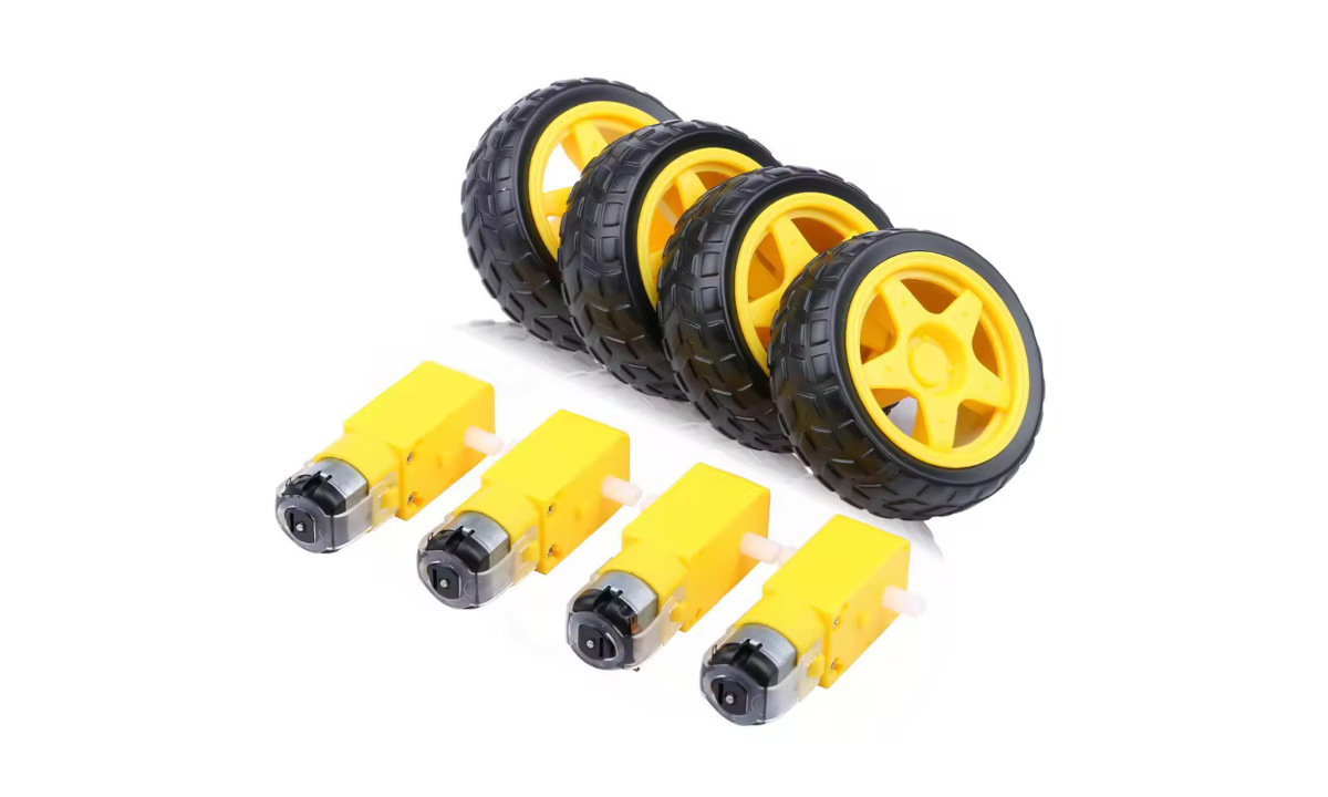
I had a kit of 4 DC motors (3-6V) with wheels in my toolbox for years. The cheap yellow set (you can find it for about 5USD, shipping included). My plan was to put these to use and it was a perfect weekend project opportunity with my daughters.
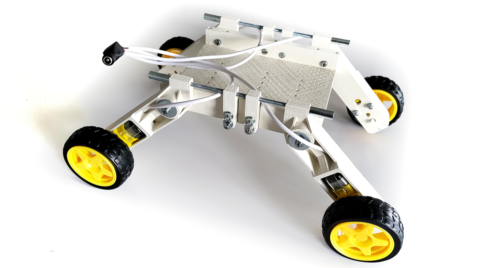
I also had some interesting ideas to build a 4×4 rover where each wheel has its own motor, but also a pivotable fixing system that allows each wheel to elevate independently in order to bypass any obstacles. Something like a leg holding a wheel and the leg then being fixed to the main rover body via some elastic pivot for improved mobility. The design part was quick and rewarding . Then first was to measure the DC motor size and holes do a quick print for test and correct any issues.
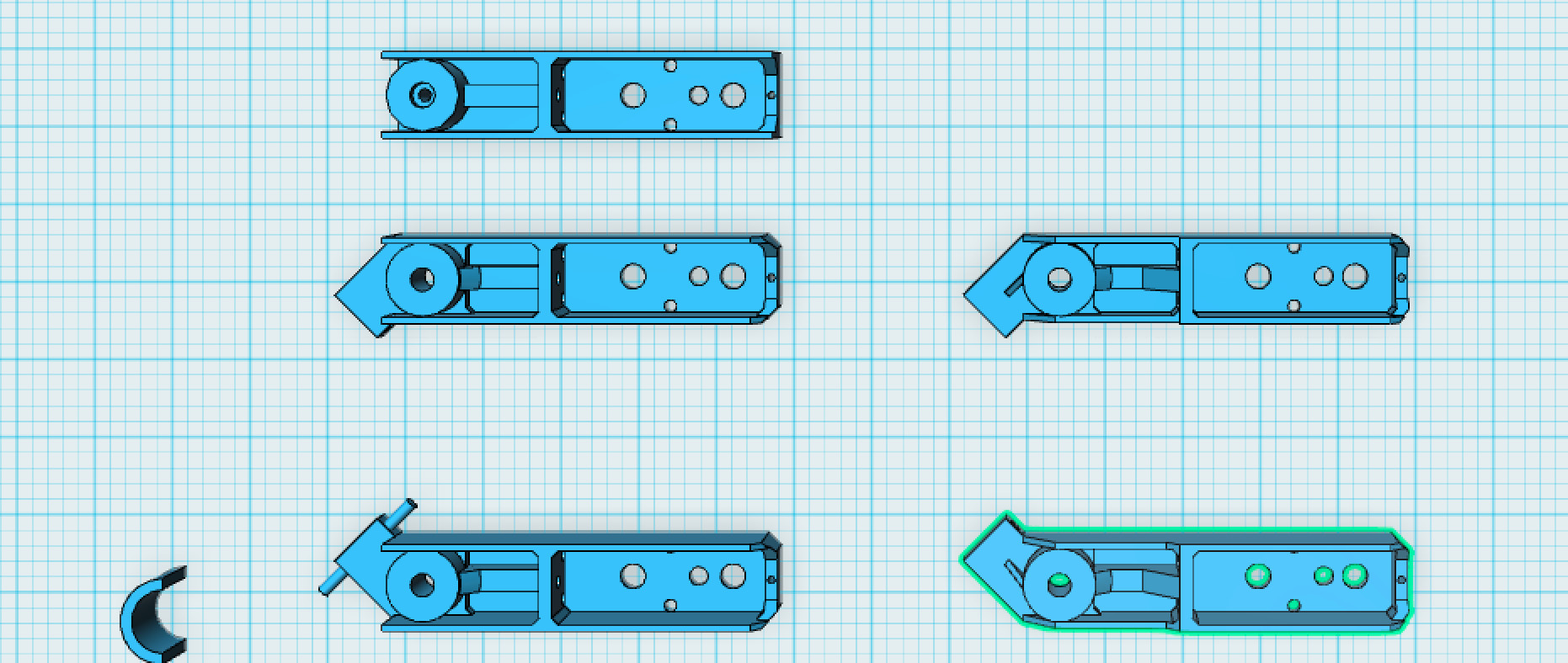
The Legs would be fixed to the main body using a custom bearing that handles all weight , done with small metallic cylinders, fixed to the main body, on which the legs would rotate freely.
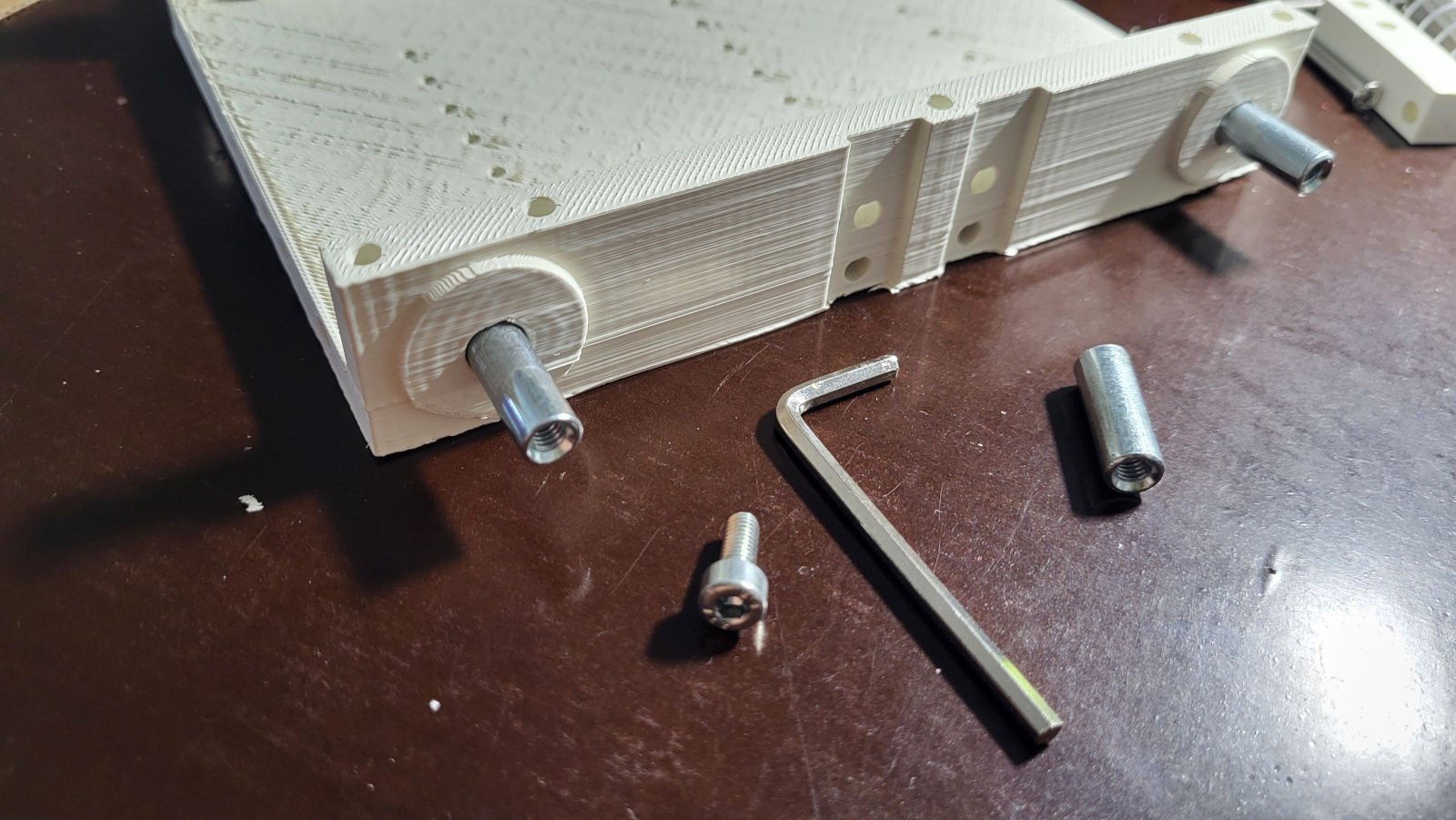
A small protuberance on each leg is intended to be connected to a spring so the leg could elevate the wheel to move up and down on an obstacle independently of the other legs.
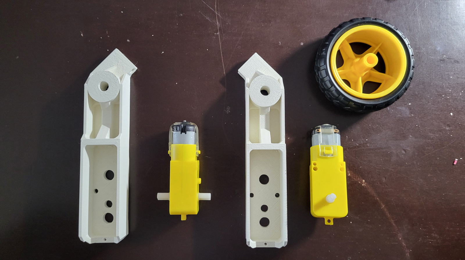
Before installing the motors, the wires were soldered, paying attention to the polarity. Each side must be connected to the same polarity, so the front and back motors move together. The rover will turn in a differential fashion, like a tank, meaning it can turn on spot. Juli did an excellent job taking care of all this, soldering the wires and assembling half of the rover:

I had several ideas in mind on the spring design, and I decided to use a elastic steel bar for the two legs on one side, connected at the middle in a rigid point, with the two ends going to the small protuberances. See the rod highlighted in green below:
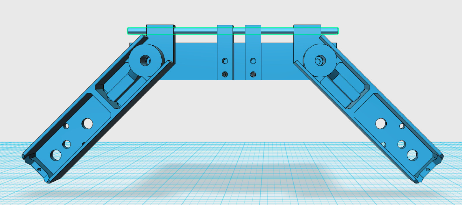
The horizontal position of the elastic bar corresponds to the normal leg position. If the legs turn a little when the wheel hits an obstacle, the elastic bar will be bent, forcing the will to return to the normal position when possible.
For the elastic rod, I recovered two 3 mm steel wires from some old composite lintels that I broke with a hammer.
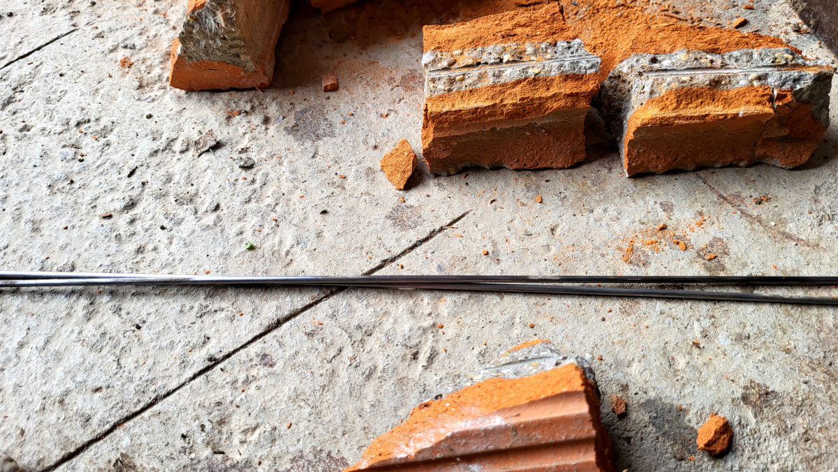
While nice and elastic, it appears they were too rigid for the intended purpose. Moving the wheels would bend them, but not in a way suited for practical use over terrain differences. A solution would be to use thinner or more elastic rods, but I had no other at this time, so I simply fixed the legs in the normal position with rigid threaded rods (2x 15cm).
If you like this design, you can build it yourself . Here is what you need:
- various screws and bolts , most of them size M4.
- 4x 15cm threaded rods (diameter 4mm).
- 4x 2cm / 7mm diameter threaded cylinders.
- 4x DC Motors + Wheels , get them here.
- a 3D printer, some filament and the 3D files for the 4 legs , the rover body and the 4 rod holders:
Here’a a little video that shows how everything is put together:
Next is to choose a microcontroller, some sensors, some battery (motors need 3-6V) , a h-bridge, and all the other nice details. It will be fun, and will post updates soon.

