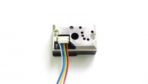
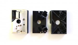
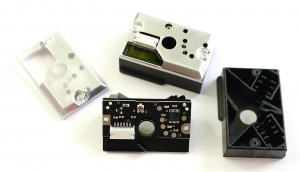
Featuring an infrared LED and, a receiving phototransistor and two lenses, this device can detect dust in air using the reflected infrared light, including very fine smoke particles. The output data patten can also be implied in smart algorithms to distinguish various types of particles. In this article I’m going to show how to connect the Sharp GP2Y1010AU0F to an AVR Microcontroller (Atmega128), how to read the output and how to convert the readings to meaningful values expressed in mg/m³. All this while using only 3.3V as input voltage.
Connecting the sensor
The connector has 6 pins, and a matching cable is included with the sensor. The colors are standard on all of the sensors I’ve seen (white, blue, green, yellow, black, red):

The datasheet presents the following diagram for connecting the sensor, where PIN1 is the white wire in our case:
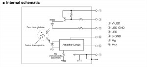
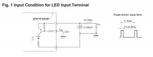
The 6 pins exposed by GP2Y1010AU0F, must be connected as follows:
White pin 1 (V-LED) => connected through a 150ohm resistor to the Vcc (3.3V)
Blue pin 2 (LED-GND) => GND
Green pin 3 (LED) => atmega128 I/O port
Yellow pin 4 (S-GND) => GND
Black pin 5 (Vo) => atmega128 ADC port
Red pin 6 (Vcc) => Vcc (3.3V)
The datasheet indicates using a 150Ohm resistor between pin 1 (white, V-LED) and Vcc (3.3V), and a 220uF capacitor . These are optional, since the device will work fine and with the same output when PIN 1 is connected directly to VCC (without resistor), and the capacitor is omitted. However the datasheet also indicates that:
In circuit designing, make allowance for the degradation of the light emitting diode output that results from long continuous operation. (50% degradation/5 years)
So it might be a good idea to use the PIN 1 V-LED resistor just to make sure the LED enjoys a longer life. For my 3.3V test circuit I’ve used an 100Ohm resistor and a 22uF capacitor. The circuit becomes:
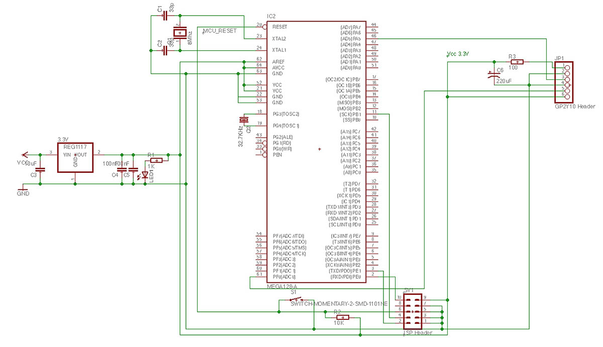
As said if your supply is well filtered, you can leave the capacitor aside.
Reading the output
This is an analogue sensor. The principle of operation is to switch the IR led on, wait a little time then read the output via the ADC port and turn the IR led off. Dust in air would shine under the focused IR light and the phototransistor would read the light output, returning a proportional voltage.
To turn the IR led on, the Green pin 3 (LED) must be pulled to GND. To turn it off, it must be pulled high (Vcc). So on our microcontroller, we need to define the controlling pin as a logical output (I selected PORTA’s PA5 on the atmega128), with an initial state of 1, so the led if off by default. Then when we want to read the dust level, we simply pull it down.
DigitalPin dust(&PORTA, PA5, DigitalPin::OUTPUT, true); // PA5 is high by default
...
int main(void) {
	aux_ADCInit(); // enable ADC so we can read the sensor's output
	dust = 0; // led on
	_delay_us(50);
	uint16_t adcValue = aux_ADCRead(PF0); // ADC conversion
	dust = 1; //led off
}
The ADC is configured for 10bit resolution and the ref is set to AVCC connected to VCC’s 3.3V. The adcValue goes from 0 (when the voltage on PF0 is 0) to 1023 (when the voltage on PF0 is 3.3V). Inserting a stick in the sensor’s hole is equivalent to the maximum dust reading (sensor totally blocked by dust) and returns a value of 772 (max being 1023).
Converting the values
Using the ADC output, we can compute the voltage on the PF0 pin (black pin 5 on the sensor).
adcVoltage = adcValue * (3.3 / 1024);
For our maximum dust level of 772, the voltage would be 2.48V . This is the maximum voltage output (with small variations depending on calibration of each particular sensor) of the GP2Y1010AU0F sensor when used in a 3.3V circuit. To interpret the readings, we head back to the datasheet that shows how to interpret the data:
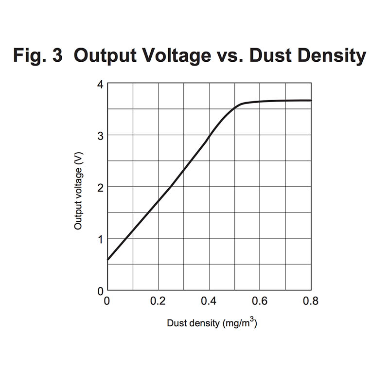
This is good to give an idea, but we have two problems:
– we have voltage and we want to know the dust concentration (the chart shows the inverse function)
– our voltage interval is 0 to 3.3V, not 0 to 5V like in the datasheet.
First, fixing the voltage output. Some sources went on uber-complicated aproaches, including dc converters and level shifters. The solution is much simpler, as ADC is a very proportional mechanism. All we need to do is to scale the output according to a 5V maximum:
adcVoltage = adcValue * (5.0 / 1024);
There, we now have 5V scaled output values , and our maximum value (with stick inserted) goes up to .. 3.76Volts, well consistent with the datasheet maximum (also note that 3.76 x 3.3 / 5.0 = 2.48, the ratio 3.3/5.0 being our scaling factor ). Having the voltage values scaled conveniently, all that’s left is interpreting them.
The datasheet function in Fig.3, shows an almost linear function in the interval [0, 0.5] . Our goal is to compute the inverse of this function, but the part from [0.5,] where the function goes quasi-horizontal is not surjective, so it cannot be inversed. But if we define the function on the [0, 0.5] only, an inverse is possible, and it looks like this:
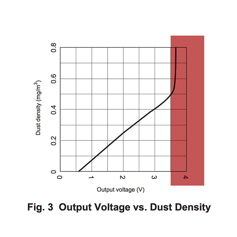
We can accept, with minor errors, a linear approximation of this function, following the blue line in the following image:
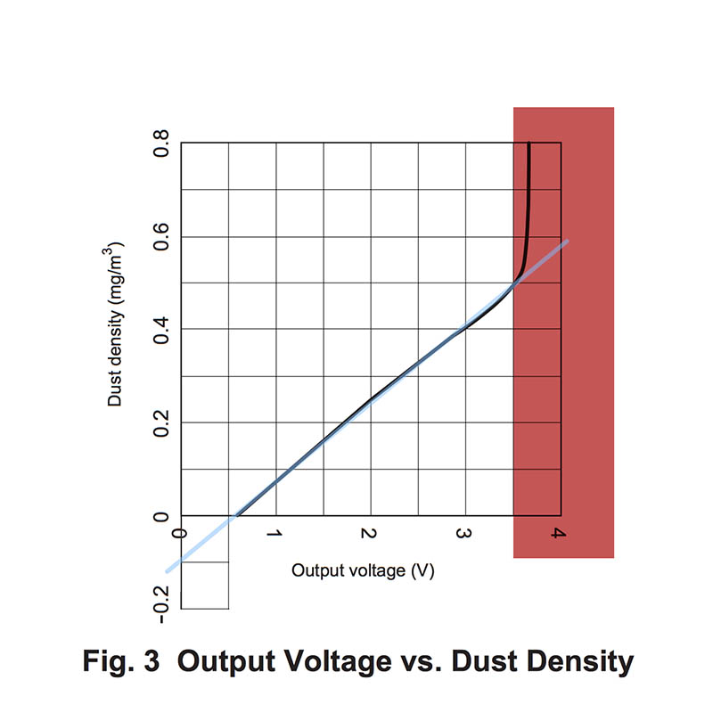
As the blue line shows a linear function, we can determine it by knowing only two points. Let’s name this function “Fl”, and it’s form is Fl(x) = a*x + b.
We need to find two points (x1, Fl(x1)) and (x2, Fl(x2)) . Given the cartesian coordinates, it’s easy to approximate the following values: x1 = 0 where Fl(x1) = -0.1 and x2 = 3.5 where Fl(x2) = 0.5 , both placed in convenient locations.
Using these two, we can compute factor a, or the slope of this function, as: a = (Fl(x2) – Fl(x1)) / (x2 – x1) or a = 0.5 – (-0.1) / 0.35 – 0 = 6 / 35 = 0.1714
Knowing a, we replace it in the function’s formula and using one of the two known points we can determine b:
Fl(x2) = a*x2 + b or 0.5 = 6/35 * 3.5 + b quickly resulting that b is -0.1
Our Fl function becomes Fl(x) = 6*x/35 – 0.1 (approximated to Fl(x) = 0.17*x -0.1), the input x is in volts and the output is the dust density in mg/m³. As dust concentration cannot be negative, we will disclose all invalid voltage values. The limit is defined by 6*x/35 – 0.1 = 0 , where x becomes 0.583 volts.
The conversion code is:
DigitalPin dust(&PORTA, PA5, DigitalPin::OUTPUT, true); // PA5 is high by default
...
int main(void) {
	aux_ADCInit(); // enable ADC so we can read the sensor's output
	dust = 0; // led on
	_delay_us(50);
	uint16_t adcValue = aux_ADCRead(PF0); // ADC conversion
	dust = 1; //led off
	adcVoltage =  adcValue * (5.0 / 1024);
	if (adcVoltage < 0.583)
		dustConcentration = 0;
	else
		dustConcentration = 6 * adcVoltage / 35 - 0.1;
}

This article has 2 Comments