An ultrasonic beacon and a ultrasonic receiver is very similar to a beam barrier circuit, the only difference is we don’t sound an alarm when an object breaks the ultrasonic path, but instead we try to locate the ultrasonic beacon by moving the receiver. This can be useful in robotics, when we use ultrasounds to detect a target (which in fact is the beacon itself).
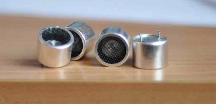
To generate or detect ultrasounds, we’ll use “40KHZ Ultrasonic Transducer Sensors”:
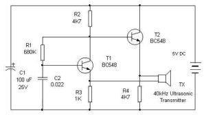
For the emitter (the beacon itself), all we need is an oscillator set for a 35-45KHz frequency. We can achieve this using a 555 timer, a microcontroller and PWM, or discrete components. The simple the better, even though we lack some control over the signal shape:
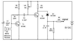
The receiver is two amplifying transistors and a detector diode:
The signal shape at the emitter:
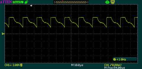
The signal at the receiver, just before the diode:
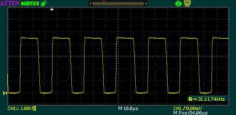
The range is excellent, at about 4 meters, the receiver was returning more than 100mV, for the detected signal, while at less than 1 meter it was putting out 4 V. The emission cone’s angle is almost 40 degrees wide. An excellent module for robotics!
Update: And speaking about robots, here are some neat ultrasonic detector modules, built for the differential rover robot I’m currently working on.
These modules can be hooked up to a microcontroller’s ADC port, and will return distance dependent voltages. So not only you can use them to spot the direction the sound is coming from, but you can also estimate the distance. The output is via the “signal” pin, which will provide approximately 0..5V depending on the power level of the detected ultrasonic signal.
I built two, as I need differential data to be able to pinpoint the source beacon easier.
![]()
![]()
![]()
![]()
Circuit diagram and PCB layout
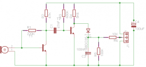
Eagle PCB layout available here: ultrasonic_beacon_receiver
Resources:
Ultrasonic Barrier
A cheap ultrasonic range finder

Hi! I work with engineering website EEWeb and would love to do an exchange of website links and feature you as a site of the day on EEWeb. Let me know if this is of interest to you! I can be reached at claire@eeweb.com
Salut Radu, am o intrebare, cam ce viteza maxima este sesizabila de senzori ? Ma refer daca as arunca cu o minge de tenis ( cu viteza 10 m/s ) printre cei doi sensori, acestia detecteaza ca a trecut un obiect pe acolo ? Multumesc
Salut Bogdan, viteza pare sa fie mare, conteaza desigur distanta intre receptor si emitator dar pentru intrebarea ta banuiesc ca ne incadram sub 4-5 metri.
Distanta dintre receptor si emitator e sub un metru. Si mai am o intrebare, conteaza natura materialul care se afla in emitator si receptor ?
Distanta dintre receptor si emitator e sub un metru. Si mai am o intrebare, conteaza natura materialului care se afla intre emitator si receptor ?
Care e natura materialului? Cred ca montajul de mai sus ar functiona bine ca si poarta detectoare. La fel de usor poti folosi si un fascicul laser.
buddy can u tell me that the tx circuit
http://www.pocketmagic.net/wp-content/uploads/2013/04/ultrasonic-transmitter.jpg
is it right or this ckt
http://www.pocketmagic.net/wp-content/uploads/2013/02/556_diagram.png
is right and what is the diffrence between them ???
thanks in advance and plzz let me know fast 🙂
@Prashant they are both correct, just different types of oscillators.
thanks bro that helped me a lot
i have an idea that if we craete a mp3 file which has pulses of 35 to 45khz and then connect the ultrasonic transducer directly to the phone and using head phone jack and play that mp3 file then the tx side ckt can be eliminated what say???
hey bro…can u help me to make this exciting robot..i need your help bro?
@Prashant, yes , it’s possible, but I don’t see the point of it: you will still need a small module for the ultrasonic transducer
@Amir, all info was provided for you to read. should you have specific questions, let me know.
Is it possible to interface these circuits with the pic16f690 micro controller for distance meassurement circuit. If so, what is the voltage produced by the receiver circuit is it 4.5volts? Thanks
Hello yes it is possible, you can connect them to any ADC port. The voltage return varies with distance. Read the article for the values I got.
Hi. i need your help. can you this circuit be upgraded so as to have a range of about 10m ?
Probably, yes.
Just a few questions
For the original reciever diagram, are the capcitor values in nano-farads, or micro-farads?
Also what is the purpose of the variable resistor? To help calibrate the input signal or does it do something else?
Thanks
the values are in micro-farads. The variable resistor is just for adjusting the sensitivity.
Is there any polarity for the transmitter? If so,which pin is the ground? And i am using 0.033uF instead of 0.022uF for transmitter circuit. Will it work or not?
sir,, what kind of transistor you used on the circuit ultrasonic reciever side.. and the diode you use??? pls help me sir in doing my project… i just currently starting my design base from your project posted in this site…
@Keyur yes. please see the datasheet
@jay ar: the eagle design files are attached at the end of the article. See all details there.
sir i downloaded the eagle design but even their,, you did not specified the kind of transistor and diode you used in the reciever.. is BC548? and for the diode,, In4148?
Sir, Would u like to share with me How you Compare both the Reciver Signa. Can i see ur Programiing..
the Recivr signal Output is connected with the A/d Converter??/
Sir would u like to Guid Me to make this Project..
My Email Id is aliansari91@yahoo.com
HEY BRO..
Can you show me.. which RX circuit that you used..im confused which one rx circuit you used..can you give the diagram..thank a lot bro
Hi radu m a beginner can u help me out building this car
hi radu…
can i use 40MHz not 40kHz transducer for this project ?
http://www.pocketmagic.net/wp-content/uploads/2013/04/ultrasonic_circuit.png
What are the transistors model in the circuit.. thanks in advance 🙂
@albhee bc548
please send me the code for your project at @qballerr@gmail.com
Hi, I’m doing a similar project and was wondering if I can contact you to get some insight regarding how to code the US receiver and transmitter.
hello Radu
I built the transmitter and receiver using the diagram u provided but when i attach cathode ray oscilloscope the receiver gives me a sinusoidal signal and when I use the transmitter in front of it i get very low amplification of the amplitude. even the range is very low can u help me with this problem?
Sir, where’s the pcb design for the receiver sir? thanks 🙂
Sorry I mean the transmitter 🙂
Sir where did you connect the Receiver? Is it directly to the Arduino Microcontroller? If so, what pins should I use?
Hobbyist here 🙂
No arduino used here. The Receiver is connected to an ADC port.
Ah, but what frequency did your transmitter emit using the 556n IC? Because using your transmitter circuit for me has very volatile frequency and emits only 60Hz frequency, sometimes 22KHz. I’ve been using 9V as a source and components are still attached to the breadboard andI don’t know what to do anymore.
Can you also send me your codes are reference? That would really help me a lot 🙂
blacklife941@gmail.com
What setting did you use for a running wavelength in the oscilloscope? Plus what part of the circuit in the eagle file should I connect the oscilloscope probes?
buddy can u tell me that the tx circuit
http://www.pocketmagic.net/wp-content/uploads/2013/04/ultrasonic-transmitter.
if 5V can be replaced by the 9V?
Hi Radu Motisan, do you know how to set a specific frequency for the receiver to receive?
Can you please send the codes. gabrieljessegatdula@gmail.com
Thank you very much.
Hi Radu,
I build a RX PCB using your circuit. It can not work. And we later found that it is because the first BJT has almost zero DC bias, while it requires about 0.7 V turn on voltage, so it can not operate correctly. If we connect the input with a AC signal with DC offset (using signal generator), it can function. Did you run into this problem before?
Thanks.
Zhihong Luo
Radu,
Even if we connect the input with a AC signal with DC bias(using signal generator), the output is very small… It looks like it is not amplified. Is there something we may make mistakes on?
Hi,Zhihong Luo
i have also made a RX just same as:
http://www.pocketmagic.net/wp-content/uploads/2013/04/ultrasonic_circuit.png
and the wave between the signal and GND is when it not receive the ultrasonic it is low level (about 200mv),when it can receive the ultrasonic it become the high level.
Sir is It possible to make a person following robot using this Ultrasonic transmitter and receiver circuit?Please help me I have a deadline for project submission.
The robot follows me in the video, is this what you are asking: http://www.pocketmagic.net/make-the-robot-follow-you/
I have referred back to this project of yours a few times for inspiration and now I have an idea. I would like to set up a wireless inductive charging station at ground level with one of these ultrasonic transmitters just above it so a small robot can easily find it’s way back to the charging station when it has low batteries and can just park there to charge. What I am wondering is if you have another circuit for the transmitter module that uses a 555 timer instead of transistors and a micro controller as I would like to keep the circuitry at the charging station as simple as possible. If not, I guess I can use an attiny85 or similar to drive the PWM. Another thought there is that the emitter at the charging dock would be off until it receives a signal from the robot, maybe from an Xbee pair to turn itself on. Anyway, can you point me to a schematic for a 555 based ultrasonic transmitter? I have probably 10 555 ICs on hand.
Thank you.
Another question regarding the transistors your schematics call out, I don’t have any BC548’s on hand but comparing datasheets, I think I can probably substitute 2N3904’s. Do you concur, or do you have another, more suitable suggestion?
Thanks again.
Hello Radu,
thanks a lot for the circuit. I have implemented the same circuits at my end but it is not working fine.Can you please guide with this ?
What exactly doesn’t work? Do you get the oscillation? What is the frequency? What do you get on the receiver?
Hello Radu,
Thanks a lot for response.Actually i am bit confused about my implemention because i am not able to see any difference in output of receiver even if some object there in between transmitter and receiver.
I am confused in below mentioned things:
1. I can see 2 receiver circuits 1 with variable resistor and other one without it(PCB layout one) which one to use ?
2. In video i can see receiver implementation with different capacitors(some yellow capacitors) while in images there are ceramic capacitors. Both of these are same ?
3.Capacitor values are in microfarad correct ?
4.i also want to know method to check ultrasonics transmitter (not including receiver)without oscilloscope just to check if it is working or not like we can check ir transmitter using mobile camera
Thanks a lot for support.
Can you please guide me on how to generate 35-40 Khz ultrasonic waves.?I am a beginner..thanxx in advance
can i buy this recevier
How much for 4? Lol I’m trying to build my girl a life size BB-8 an an these are EXACTLY what I’m looking for!!!!
Shoot me an e-mail if u could!!!