Pictures:
Details:
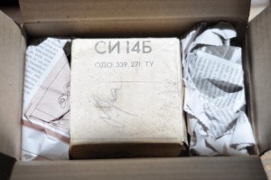
The SI-14B was designed for measurement of soft beta-radiation for wide application in the field of radiation dosimetry.
Datasheet:
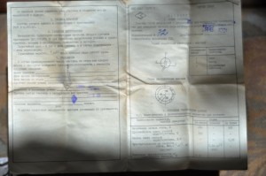
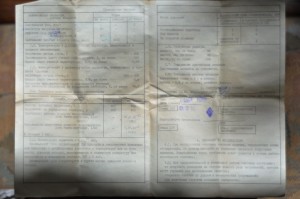
Temperature: -40ºC to +70ºC
Relative humidity: up to 90%;
Atmospheric pressure: from 0.67 kPa to 294kPa
Operating voltage range: 350V-550V
Slowness plateau counting response: no less than 160V
The slope of the plateau counting response: 0.25% / V
EDR – 1000r / h
Sensitivity at 1mkR / s : 300imp / s
Diameter: 84mm
Length: 26mm
Weight: 133g
Links:
n/a

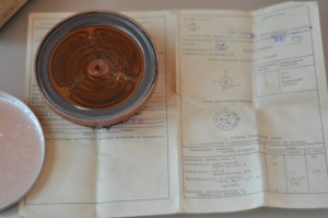
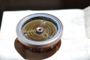
I thought this is a pancake recipe :))
Nope, this one’s not edible 🙂
Perhaps the tube is not self-quenching. This means that it has to be “reset” after each ionization event.
See here…
http://en.wikipedia.org/wiki/Geiger-M%C3%BCller_tube
That third electrode is strange for a Geiger Muller tube, so perhaps has something to do with quenching.
Hi Gaston, indeed the tube is not recovering after a discharge. I believe this has self-quenching capabilities probably with some halogen gas, but this mixture has been altered by the high voltage applied to this tube. You can see how bad the electrodes look. It’s there where the recovery doesn’t take place, and a multitude of fake discharges are produced.
Regarding the third electrode, it is used for Beta particle detection, to pre-ionise the gas mixture. It is explained in the russian data sheet, I was able to extract a few details.\
I will see if I have better luck with the smaller tube, after all these are very old tubes.
Hi Radu
Interesting! I am just building a Geiger Counter (based on Arduino + 8×2 display) for exactly this tube and it works. I found I need to keep the voltage between 450 and 550 to get the best out outcome – altough its a bit hard to exactly masure the voltage … even my DVM as part of a 90M voltage divider has difficulties showing me a reliable reading …
I have not found a problem with these avalanches but would appreciate if someone managed to translate the russion document that came with it.
I will post the design+details of this project once it’s in a nice box and ready to go (the mechanics need to be sorted out now).
Cheers Jampac
Hi Jampac, thanks, looking forward to see your setup!
I have the original russian document, I might try to scan it and do an OCR before a google russian->english translation. hope that works.
Is there any particular details from the datasheet, you are interested in ?
Have you handled the third electrode? It is used to enhance the beta particle detection capabilities.
For my setup I only plan to use the anode and the cathode.
Cheers!
Radu
Hi Radu – I am using only the anode/kathode and is working well so far. Currently running at 600V (a bit much maybe) stabilised by 3 200V Zener Diodes + 10M. The signal conditioning was a bit of a challange – a dual oscilloscope was a big help to adjust the low pass/smitt trigger 4069 combination. I am particular interested in the min/best/max voltage and the use of the third electrode. Also if there is information on the data sheet outlining the relationship between counts to roentgen. I am using a thorium lantern mantle showing 7uSV/h measured by two other Geiger counters (one of them was recently calibrated) – this gives about 22000 CPM on the SI4B. Of course we are not comparing apples with apples as the SI4B also detects alpha.
Cheers Jampac
Indeed 600V is a bit too much (350V-550V is recommended in the datasheet). What is the date your tube was manufactured?
My high voltage supply was set to 480V, but I had issues with avalanche discharges because my tube was damaged. I now have a smaller SI12B that I plan to use, because of their excellent mica windows.
From what I read, the third electrode is only needed for detecting Beta particles.
Would love to see your setup, feel free to post pictures at any time!
Hi friend!
Your Geiger tube CI14B is non self quenching. It’s actually gas triode-like Geiger tube. You have to make a circuit for quenching it. Basically theory of operation is simple. When ionizing event take place it produces avalanche, and anode current increases. That increase produces voltage drop on anode resistor and triggers one shot circuit or better Schmidt trigger. Pulse from this circuit opens one transistor which connect control electrode (electrode no. 3 on your tube) to high voltage (200-400V) and choke avalanche that took place in tube. This is great because tube life is very very long in compare to halogen quenched tubes, but bad thing is that quenching circuit will produce longer dead time. You’ll have about 250us instead of 80-100us. Please tell me where to buy this tube, i need few for my students.
hi Ivan, thanks for the feedback. I’ve seen some of these tubes on Ebay.
I would need more info on the CI14B, do you have any schematics that I could use? I had no idea it is not self quenching.
I found tube that is very similar to CI14B in my lab, connect it to high voltage, and it acts like you described. I was hoping that I’m wrong, but it is actually non self quenching Geiger tube. Give me few days to experiment with exact quenching circuit, and I’ll send you mail (as an ExpressPCB file). If you wanna tube for some real measurements, that is highly sensitive, tested and self quenching, you should use Ludlum LND7312 tube.
Ivan, do you have any news or progress on this?
Radu, I have few problems in my lab at the university, so I canceled any experiments with quenching circuits. At the moment I have few working circuits but with electron tubes. Those circuits had been used in manhattan project geiger counters. Probably the best circuit is ‘Neher-Pickering’ design, but it employs triode as a switching element. My colegues from Russia experiment with semiconductor devices for quenching and they send me circuit diagram I haven’t tried yet. This circuit is a little complicated. When pulse is detected, circuit reverse polarity of the tube, so the slow positive ions are collected at the wire of the tube. This act is simmilar to ‘normal’ quenching, and they clame that dead time with this device is about 10us…. As soon as I try this device, I’ll send you!
Hello Ivan,
I would like to move forward and run some tests with the tube I have. Could you send me the circuit diagram, it’s ok even if it is with tubes.
Thank you,
Can someone please tell me the functions of the three terminals on the S114B.
I believe terminal three is anode (+450V) and one of the others will be the cathode, but what does the third terminal actually do ?
What effect does it have, and what is the recommended voltage for the third terminal ?
Cheers, Tony.
Does anyone know the real difference between the SBM-20 and the SBM-19 in ability to perceive radiation? Also, is there a way to filter out beta and gamma, leaving only the alpha? (I know that these two are not very sensitive to alpha, as a rule)
I’m currently putting another one together, but it’s not Arduino based. It’ll have a meter, led, and speaker output and provision for sending pulses to a computer for logging. Everything I read says the SBM-19 is much better than the SBM-20. I would love to know if anyone out there has had actual experience with the two tubes.
@tony
The third terminal regulates the sensivity.You can apply 200 Volts for lower sensivity and 400 Volt for maximum sensivity.
Number one is the Anode and number 2 and three are Kathodes.Number three ist this one,for regulation the sensivity